OLC - D OTDR Launch Cable
If you are installing an outside plant network such as a long distance network or a long campus LAN with splices between cables, you will want an OTDR to check if the fibers and splices are good. The OTDR can see the splice after it is made and confirm its performance. It can also find stress problems in the cables caused by improper handling during installation. If you are doing restoration after a cable cut, the OTDR will help find the location of cut and help confirm the quality of temporary and permanent splices to restore operation. On singlemode fibers where connector reflections are a concern, the OTDR will pinpoint bad connectors easily.
Since so little of the light comes back to the OTDR for analysis, the OTDR receiver circuit must be very sensitive. That means that big reflections, which may be one percent of the outgoing signal, will saturate the receiver, or overload it. Once saturated, the receiver requires some time to recover, and until it does, the trace is unreliable for measurement.
The most common place you see this as a problem is caused by the connector on the OTDR itself. The reflection causes an overload which can take the equivalent of 50 meters to one kilometer to recover fully, depending on the OTDR design, wavelength and magnitude of the reflection. It is usually called the "Dead Zone". For this reason, most OTDR manuals suggest using a "pulse suppresser" cable, which doesn't suppress pulses, but simply gives the OTDR time to recuperate before you start looking at the fiber in the cable plant you want to test. They should be called "launch" cables.
Do not ever use an OTDR without this launch cable! You always want to see the beginning of the cable plant and you cannot do it without a launch cable. It allows the OTDR to settle down properly and gives you a chance to see the condition of the initial connector on the cable plant. It should be long, at least 500 to 6000 meters to be safe, and the connectors on it should be the best possible to reduce reflections. They must also match the connectors being tested, if they use any special polish techniques.
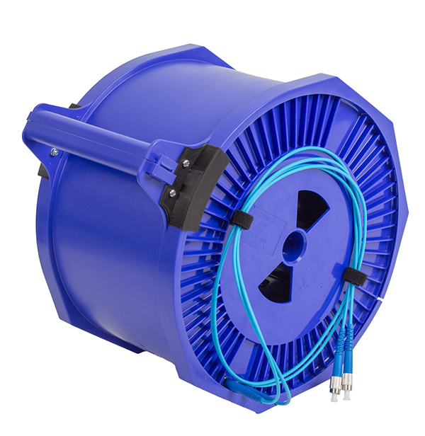
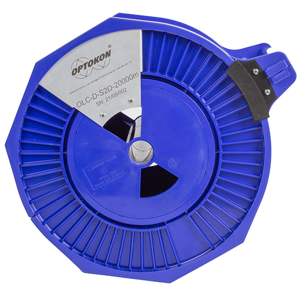
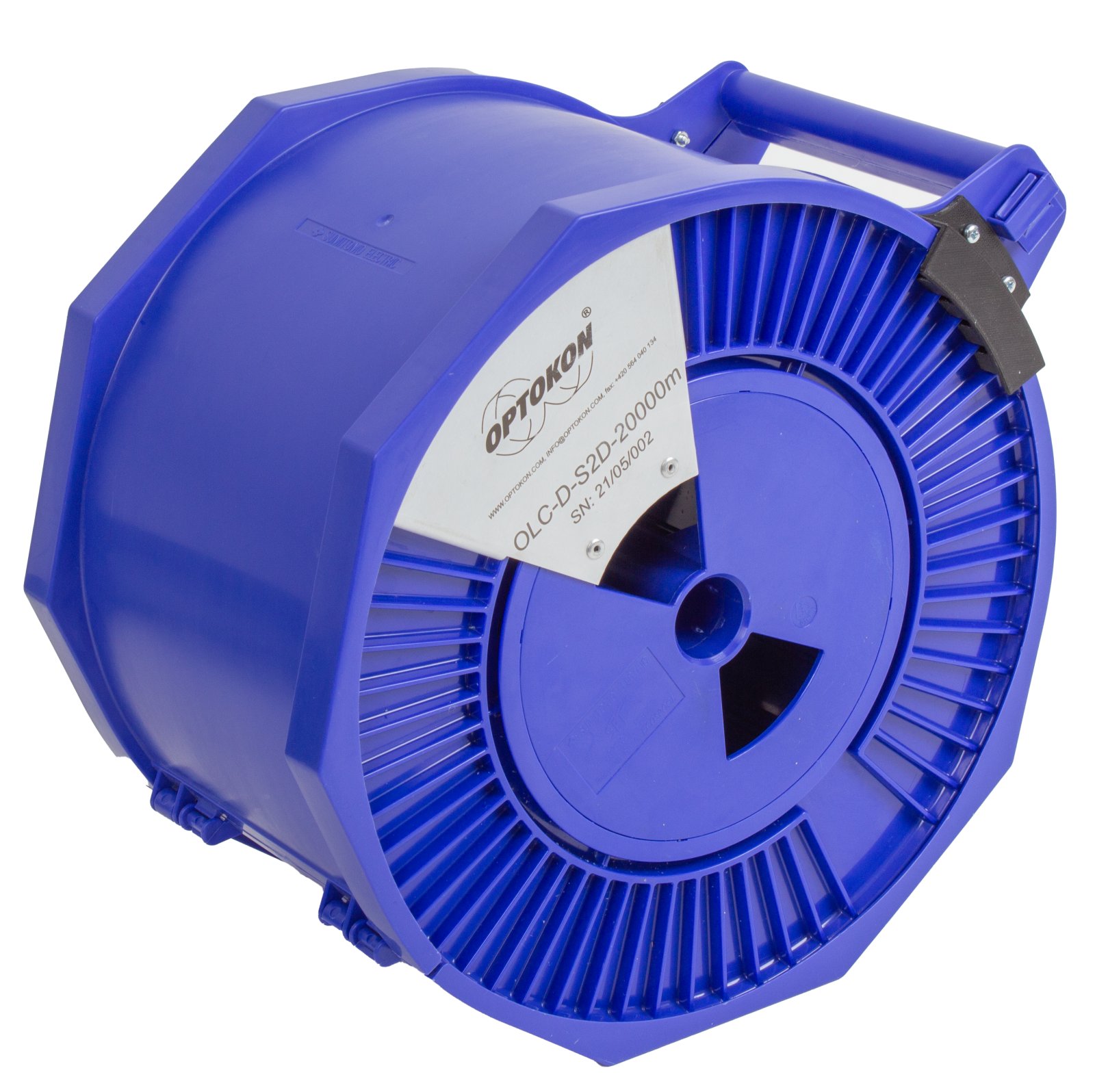
- Plastic drum with handle
- The length of launch cable defined by the customer.
- Various types of optical connectors offer increased versatility and convenience.
- Optical connectors are dust and drop protected by a snap-on cover.
|
Parameter |
unit |
Note |
|
Total fiber length |
m |
up to 50 km (primary coated fiber 250 µm) |
|
Fiber length tolerance |
m |
±2.5% (min. 50 m) |
|
IN/OUT pigtail length |
m |
1.0 ±0.2 |
|
IN/OUT pigtail diameter |
mm |
2.8 |
|
IN/OUT connectors1 |
|
Refer to request |
|
Connectors Insertion loss |
dB |
following OPTOKON technical specification according connector type |
|
Connectors Return loss |
dB |
following OPTOKON technical specification according connector type |
|
Operating Temperature |
°C |
-20 to +70 |
|
Cable drum size |
mm |
275 x 180 x 320 |
|
Cable drum weight |
kg |
1.8 (10 km), 2.5 (20 km), 3.2 (30 km), 4.6 (50 km) |
- OTDR measurements
- Insertion loss testing
- Return loss testing
- Fault locations and fault clearance
|
OLC-D |
- |
AAA |
/ |
AAA |
- |
XX |
- |
XXXXX |
|||||||||
|
|
|
|
|
|
|
|
|
|
|||||||||
|
IN/OUT connector types1 |
|
|
Fiber type: |
|
Length2 (m) |
||||||||||||
|
|
|
|
|
|
OM1 |
MM 62.5/125 |
|
|
|||||||||
|
Note: |
|
OM2-4 |
MM 50/125 |
|
|
||||||||||||
|
|
S2D |
SM (G.652D) |
|
|
|||||||||||||
|
|
S7xx3 |
SM (G.657..) |
|
|
|||||||||||||
|
|
S5 |
SM (G.655) |
|
|
|||||||||||||
|
|
other |
please specify |
|
|
|||||||||||||
Example:
OLC-D-UPC/UPC-S2D-50000
Single mode launch cable: FC/UPC – ultra polished FC connectors, Grade B FC/UPC connector: IL < 0.25 dB, RL > 50 dB, SM G.652D fiber, 50 000 m length