OLC - M(P) Mini OTDR Launch Cable
If you are installing an outside plant network such as a long distance network or a long campus LAN with splices between cables, you will want an OTDR to check if the fibers and splices are good. The OTDR can see the splice after it is made and confirm its performance. It can also find stress problems in the cables caused by improper handling during installation. If you are doing restoration after a cable cut, the OTDR will help find the location of cut and help confirm the quality of temporary and permanent splices to restore operation. On singlemode fibers where connector reflections are a concern, the OTDR will pinpoint bad connectors easily.
OLC-P-NLC/NSC-S7A-500
Since so little of the light comes back to the OTDR for analysis, the OTDR receiver circuit must be very sensitive. That means that big reflections, which may be one percent of the outgoing signal, will saturate the receiver, or overload it. Once saturated, the receiver requires some time to recover, and until it does, the trace is unreliable for measurement.
The most common place you see this as a problem is caused by the connector on the OTDR itself. The reflection causes an overload which can take the equivalent of 50 meters to one kilometer to recover fully, depending on the OTDR design, wavelength and magnitude of the reflection. It is usually called the "Dead Zone". For this reason, most OTDR manuals suggest using a "pulse suppresser" cable, which doesn't suppress pulses, but simply gives the OTDR time to recuperate before you start looking at the fiber in the cable plant you want to test. They should be called "launch" cables.
Do not ever use an OTDR without this launch cable! You always want to see the beginning of the cable plant and you cannot do it without a launch cable. It allows the OTDR to settle down properly and gives you a chance to see the condition of the initial connector on the cable plant. It should be long, at least 500 to 1000 meters to be safe, and the connectors on it should be the best possible to reduce reflections. They must also match the connectors being tested, if they use any special polish techniques.
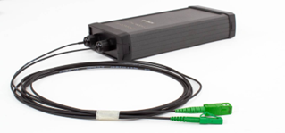
The OLC-M/P, compact pocket size OTDR launch cable is designed for easy handling and carrying. Its robust design ensures reliability and endurance. Protective caps helps keeping connectors clean. This launch cable is fully compatible with almost all OTDRs.
Specially with OPTOKON MOT-500 Mini OTDR series the OLC-M/P introduces an useful and powerful set for OTDR measuring in optical networks.
- Portable packaging – small, lightweight design
- The instrument's ergonomic design fits comfortably in hand for extended periods.
- The length of launch cable defined by the customer.
- Various types of optical connectors offer increased versatility and convenience.
- Optical connectors are dust and drop protected by a Snap-on cover.
|
Parameter |
Unit |
Note |
|
Fiber length |
m |
L ± 50 m |
|
Connectors Insertion loss |
dB |
following OPTOKON technical specification according connector type |
|
Connectors Return loss |
dB |
following OPTOKON technical specification according connector type |
|
Operating Temperature |
°C |
-20 to +70 |
|
|
|
|
|
Loss accuracy – SM (1310/1550 nm), MM (850/1300 nm) |
||
|
Backscatter measurements 1 dB steps |
dB |
± 0.05 dB |
|
Reflectance measurements |
dB |
± 2.0 dB |
|
Dimensions (W x H x D): OLC-M, OLC-P OLC-PE |
mm |
fiber length up to 2000 m 190 x 102 x 37 270 x 246 x 124 |
Example:
OLC-P-UPC/UPC-S7A-1000
G.657A1 SM launch cable, cable connectors interface, 1000 m length:
UPC – ultra polished FC connector IL = 0.15 dB, RL > 50 dB
OLC packaging:
 |
 |
 |
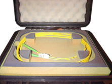 |
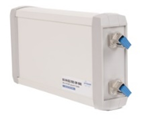
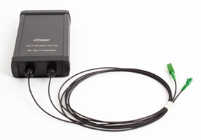
| OLC-M-USC/USC-S7A-500 | OLC-P-NLC/NSC-S7A-500 | OLC-PE-NE2A/NE2A-S2D-2000 | |
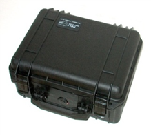
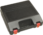
Options:
additional case for OLC-M, OLC-P
TE-HC-02/1 plastic case, 265 x 280 x 95 mm (WxDxH)
- OTDR measurements
- Insertion and return loss testing
- Fault locations and fault clearance
|
OLC-X |
- |
AAA |
/ |
AAA |
- |
XX |
- |
XXXX |
|
|
|
|
|
|
|
|
|
|
|
|
|
|
IN/OUT1 interface: |
|
|
|
Length2 [m] |
||||
|
|
|
|
|
|
|
|
|||
|
OLC-M adapter |
|
Fiber: |
|
||||||
|
OLC-P connectorized cable |
|
OM1 |
MM 62.5/125 µm |
||||||
|
OLC-PE OLC in Peli case |
|
OM2-4 |
MM 50/125 µm |
||||||
|
|
|
|
|
||||||
|
|
|
|
|
|
S7X3 |
SM 9/125 µm (G.657X) |
|||
|
|
|
|
|
|
S2D |
SM 9/125 µm (G.652D) |
|||
|
|
|
|
|
|
S5X3 |
SM 9/125 µm (G.655X) |
|||
|
|
|
|
|
|
S6X3 |
SM 9/125 µm (G.656X) |
|||
Note:
1) Connector type according relevant datasheet: CON_13-01_EN - ORD_CODE
2) MM fiber – at least 200 m, SM fiber – at least 500 m
3) X – according fiber subtype
