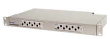
MCNP - Rack Mount Connector Network Panel
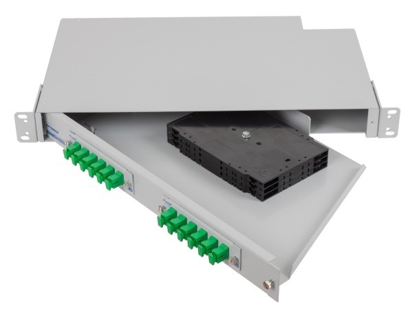
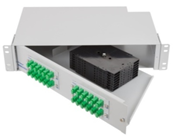
The MCNP Connector Network Panel is an economical rack mountable ODF – optical distribution frame for use with splicing of manufactured pigtails, pre terminated cables and field-installable connectors. Made of lightweight and resistant aluminum alloy the MCNP offers user friendly handling during installation and operation and low transportation costs. The incoming cables are strain-relieved at the rear panel of the unit. The pivoting shelf can be equipped with either a splice tray holder or bend radius protection which guides, stores and organizes excess slack. This prevents damage to fibers prior to routing into couplings. The MCNP is used in installations where space is limited.
- Splicing and termination optical cable in one box
- Pivoting shelf eases connector routing and cable routing
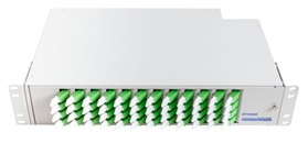
- Extended (3 coupling panels per 1U) version available
- Version for installation of adaptors under angle
- Accommodates up to 48 fibers in 1 rack unit
- Splice cassette holder enables cable termination with the help of pigtail splicing
- Made of lightweight aluminum alloy
- Protection: IP20
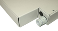
- Cable strain-relief and grounding provisions
- Accepts the industry's most common connector types
- FTTH use – microtubes holder included
- Passed seismic tests according to ASME standards
- Aluminium alloy material-low weight and shipment costs
- Durable powder coat finish light grey colour (RAL 7038, RAL 9006), next color option: ADAPTA DX-7182-XW color based on saturated polyester resins – stainless steel look
- Operating temperature -40 to +85 °C
|
PART NUMBER |
FIBER CAPACITY2+4 |
RACK UNITS |
DIMENSIONS (HxWxD) mm |
SHIP WGT (kg) |
|
|
CNPM-XX-063 |
CNPM-XX-083 |
||||
|
MCNP – 1S |
12 (24) |
16 (32) |
1 |
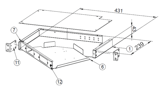
44 x 432 x 239 |
2.4 |
|
MCNP – 2S |
24 (48) |
32 (64) |
2 |
88 x 432 x 239 |
3.8 |
|
MCNP – 3S |
36 (72) |
48 (96) |
3 |
133 x 432 x 239 |
5.2 |
|
MCNP – 1E |
18 (36) |
24 (48) |
1 |
44 x 432 x 239 |
2.4 |
|
MCNP – 2E |
36 (72) |
48 (96) |
2 |
88 x 432 x 239 |
3.8 |
|
MCNP – 3V |
72 (144) |
96 (192) |
3 |
133 x 432 x 239 |
5.5 |
|
MCNP – 1A5 |
Special FPs - angled adaptors without screws, no CNPM panels |
1 |
44 x 432 x 239 |
2.4 |
|
Note:
1) Conditioned by temperature range of cable type
2) Splice Tray: CMS_01-09_EN-KNS Splice_trays
3) CNPM coupling panel: CMS_24-01_EN-CNPM
CNPM-XX-06 6 pcs ST, FC, SC, E2000, DLC ... adapters
CNPM-XX-08 8 pcs ST, FC, SC, E2000, DLC... adapters
4) Fiber capacity depends on connector adaptor type, e.g. in the case DLC it is double capacity.
5) MCNP-1A, 2A
Special front panel with angle mount adaptors without screws, CNPM panels not used in this variants,
for all standard adaptor types (SC, DLC, E2000, FC, etc.)
 |
|
|
|
 |
| MCNP-2A-48-E2 A-C-4 /A |
MCNP-2S-24-SC A-C-6 /A |
MCNP-1S /A /ADAPTA DX-7182XW color |
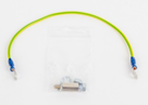
Grounding accessories |
P-Rodent protected version, cable entry |
|
|
Parts which are available separately: 1 OCNP-BU-X base unit |
|
MCNP |
- |
XX(P)7 |
- |
XX |
- |
XX(F)6 X - |
|
X - XX |
/A / /G8 /(7182)9 |
||||||||
|
|
|
|
|
|
|
|
|
|
|
||||||||
|
Version |
|
|
|
|
|
|
|
X - Option for Fiber Termination |
|||||||||
|
Rack Unit |
|
Type |
|
|
|
|
|
|
|
B |
Bend radius protectors |
||||||
|
1 1U |
|
S Standard (2 panels per 1U) |
|
|
|
|
|
C |
Splice cassette for 12 splicing |
||||||||
|
2 2U |
|
V Vertical (12 panels per 3U) |
|
|
|
|
|
XX - Number of Splice Cassettes (for „C” option) |
|||||||||
|
3 3U |
|
E Extended (3 panels per 1U) |
|
|
|
|
|
0 |
No cassette |
||||||||
|
|
|
A Angled (no CNPM panels) P Protected |
|
|
|
|
|
|
(only splice holder) |
||||||||
|
|
|
|
|
|
|
|
|
1 - 3 |
Number of Splice Cassettes for 1U |
||||||||
|
|
|
Fiber Capacity |
|
|
|
|
|
1 - 8 |
Number of Splice Cassettes for 2U |
||||||||
|
|
|
12, 24,... fibers |
|
|
|
|
|
1 - 12 |
Number of Splice Cassettes for 3U |
||||||||
|
|
|
|
|
|
|
|
|
|
|
Note: 6) F - Fixed adaptors by screws (no for 2A ver.) 7) P - Optional, rodent protected (with PG 13,5) 8) G – Grounding option – protection grounding wires installed 9) Option – color ADAPTA DX-7182-XW
|
|||||||
|
|
|
Coupling Type |
|
|
|
|
|
||||||||||
|
|
|
XX |
|
|
|
X |
|
|
|
||||||||
|
|
|
ST |
ST |
|
M Multimode |
|
|||||||||||
|
|
|
SC(F) |
SC |
|
S Single mode |
|
|||||||||||
|
|
|
FC |
FC |
|
A APC |
|
|
||||||||||
|
|
|
E2(F) |
LSH (E2000) |
|
|
|
|||||||||||
|
|
|
MJ |
MT-RJ |
|
|
|
|
|
|||||||||
|
|
|
DSC(F) |
Duplex SC |
|
|
|
|
|
|
|
|
|
|||||
|
|
|
DLC(F) |
Duplex LC |
|
|
|
|
|
|
|
|
|
|||||
|
|
|
DMU(F) |
Duplex MU |
|
|
|
|
|
|
|
|
|
|||||
