Copper SFP+ Transceivers RJ-SP-10GBASE-T
OPTOKON’s Copper Small Form Pluggable (SFP+) transceivers are based on the SFP Multi Source Agreement (MSA). They are compatible with the 10Gbase-T standards as specified in IEEE Std 802.3 . RJ-SP-10GBASE-T uses the SFP's RX_LOS(must be pulled up on host) pin for link indication. If pull up or open SFP's TX_DISABLE pin, PHY IC be reset.
Temperature
|
Name |
Min |
Max |
Unit |
Notes/Conditions |
|
Operating Temperature |
0 |
65 |
|
Case temperature |
|
Storage Temperature |
-40 |
85 |
|
Ambient temperature |
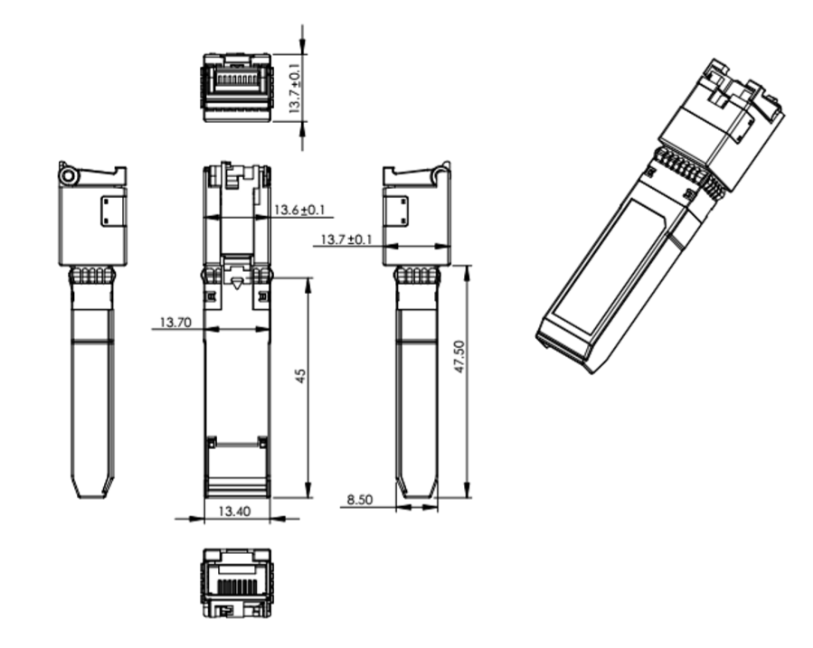
Dimmension
SFP+ HOST Connector Pin Out
|
PIN |
Symbol |
Name/Description |
Ref |
|
1 |
VEET |
Transmitter Ground (Common with Receiver Ground) |
1 |
|
2 |
TFAULT |
Transmitter Fault. Not supported. |
|
|
3 |
TDIS |
Transmitter Disable. Laser output disabled on high or open. |
2 |
|
4 |
MOD_DEF(2) |
Module Definition 2. Data line for Serial ID. |
3 |
|
5 |
MOD_DEF(1) |
Module Definition 1. Clock line for Serial ID. |
3 |
|
6 |
MOD_DEF(0) |
Module Definition 0. Grounded within the module. |
3 |
|
7 |
Rate Select |
No connection required |
|
|
8 |
LOS |
High indicates no linked. low indicates linked. |
|
|
9 |
VEER |
Receiver Ground (Common with Transmitter Ground) |
1 |
|
10 |
VEER |
Receiver Ground (Common with Transmitter Ground) |
1 |
|
11 |
VEER |
Receiver Ground (Common with Transmitter Ground) |
1 |
|
12 |
RD- |
Receiver Inverted DATA out. AC Coupled |
|
|
13 |
RD+ |
Receiver Non-inverted DATA out. AC Coupled |
|
|
14 |
VEER |
Receiver Ground (Common with Transmitter Ground) |
1 |
|
15 |
VCCR |
Receiver Power Supply |
|
|
16 |
VCCT |
Transmitter Power Supply |
|
|
17 |
VEET |
Transmitter Ground (Common with Receiver Ground) |
1 |
|
18 |
TD+ |
Transmitter Non-Inverted DATA in. AC Coupled. |
|
|
19 |
TD- |
Transmitter Inverted DATA in. AC Coupled. |
|
|
20 |
VEET |
Transmitter Ground (Common with Receiver Ground) |
1 |
|
Part number: |
Speed [Mbps] |
Distance [m] |
Cable type |
Host port |
Temperature[i] |
|
RJ-SP-10GBASE-T |
10000 |
80 |
CAT6A |
10GBASE-R |
-10 to +70° C |
Automatic crossover detection is enabled. External crossover cable is not required
1. Circuit ground is connected to chassis ground
2. PHY disabled on TDIS > 2.0 V or open, enabled on TDIS < 0.8 V
3. Should be pulled up with 4.7k – 10k Ohms on host board to a voltage between 2.0 V and 3.6 V. MOD_DEF(0) pulls line low to indicate module is plugged in.
