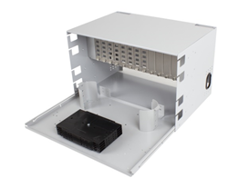
MFDC – Splice and Termination Cabinet
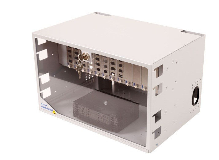
The MFDC cabinet offers termination and splicing within one convenient housing. The MFDC terminates up to 144 fibers in 6U frame. This unit accepts 12 snap-in coupling panels or prewired cassettes. Fibers are routed to the lower section of the unit where splice trays, fiber bundles, and buffer tubes are stored. Splice trays can be located on a pullout shelf, allowing easy access to the buffer tube, fiber storage and splicing area.
- Aluminum material providing low weight and low shipping costs
- Accommodates up to 144 fiber splices
- Splicing in single splice trays X1B
- Individual splice tray access
- Removable top and back cover allows unrestricted front, rear and top access
- Prewired CAPM cassettes include connectorized fiber pigtails and adapters
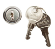
- Key lock and metal latch door options are available
- Durable powder coat finish
- Labels provided to document splice and termination locations
|
PART NUMBER |
RACK UNIT |
DIMENSIONS (H x W x D) mm |
SHIP WGT (kg) |
Purpose |
|
MFDC |
6U |
267 x 432 x 305 |
2.9 |
Splice & termination |
Equipment parameters
|
Cassette type |
Number of cassettes |
Splicing capacity |
|
Cassettes X1B1 |
12 |
144 |
|
Patch panel type |
Number of patch panels |
Termination capacity |
|
CNPM-XX-06 |
12 |
72/1442 |
|
CNPM-XX-08 |
96 |
Note: 1) Details see datasheet CMS_21-01_EN-Splice trays
2) When duplex adaptors are used
|
|
|
 |
 |
|
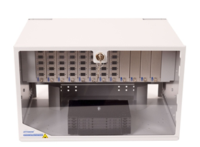
Closed MFDC with plastic door and keys |
MFDC with the pulled out shelf |
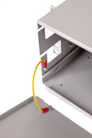
Grounding wiring detail | |
|
MFDC |
- |
X |
- |
XXX |
- |
XX(F)1-X |
- |
|
XX |
- |
/(G)2 - (UHV)3 |
||||
|
|
|
|
|
|
|
|
|
|
|
|
|
||||
|
Version |
|
|
|
|
|
|
|
|
|
Front Door Option |
|||||
|
MFDC |
Standard 12x panels, |
|
|
|
|
|
|
|
|
|
LM |
Metal door – lock |
|||
|
Sliding shelf, Cassettes |
ZM |
Metal door – latch |
|||||||||||||
|
|
|
|
|
|
|
|
|
|
|
LP |
Plastic door – lock |
||||
|
|
|
|
|
|
|
|
|
|
|
ZP |
Plastic door – latch |
||||
|
|
|
|
|
|
|
|
|
|
|
|
|
||||
|
|
|
|
|
|
|
|
|
|
Applications |
||||||
|
X - Number of Splice Trays |
|
|
|
|
|
|
M |
Multimode |
|||||||
|
1 ÷ 12 Number of splice trays X1B |
|
|
|
|
|
|
S |
Singlemode |
|||||||
|
|
|
|
|
|
|
A |
APC applications |
||||||||
|
|
|
|
|
|
|
|
|
|
|||||||
|
|
|
|
|
|
Coupling Type |
||||||||||
|
|
|
|
Fiber Capacity |
|
|
ST |
ST adapter |
||||||||
|
|
000 – 144 Fibers |
|
|
SC(F) |
SC adapter |
||||||||||
|
|
|
|
FC |
FC adapter |
|||||||||||
|
|
|
|
E2(F) |
E2000 adapter |
|||||||||||
|
|
|
|
DSC(F) |
SC duplex adapter |
|||||||||||
|
|
|
|
DLC(F) |
LC duplex adapter |
|||||||||||
|
|
|
|
DE2(F) |
Duplex E2000 |
|||||||||||
|
|
|
|
|||||||||||||
|
Key lock(LM) |
Metal latch(ZM) |
|
|
|
|||||||||||

Note:
1) „F“ Fixed adaptors by screws
2) G – Grounding option – protection grounding wires installed, see datasheet CMS_01-02_EN-accessories
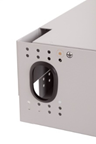
3) UHV – Vertical unit holder
4) Optional –The same key for multiple ordered cabinets
