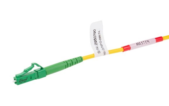
Master LC Patchcord
We offer an extensive range of pre-terminated cable assemblies that are 100% tested to ensure conformance with your specifications. These assemblies are used for measuring and manufacturing of fiber optic components and optical network testing.
The Master patchcord is equipped with a Master connector according to the specifications below. The master connector is marked and specified with its Serial Number, which ensures traceability of transmission and geometrical parameters. The second connector is a standard type. For the hybrid patchcord version different types of master and standard connector types are also available.
|
Insertion loss2 (IL) |
SM Ultra PC |
SM Angle PC |
|
0.10 dB max |
0.10 dB max |
|
|
Return loss2 (RL) |
≥ 55 dB1 |
≥ 70 dB1 |
|
PDL2 |
max 0.1 dB |
|
|
Strain relief |
max 90 N |
|
|
Allowable input power |
max 1.0 W |
|
|
Strain relief |
100 N |
|
|
Operating temperature |
-30°C to +70°C |
|
|
Durability |
min 1000 cycles |
|
|
Assembly procedure |
glue and polish |
|
|
Connection |
physical contact |
|
|
Lock mechanism |
snap-on |
|
|
Standards |
IEC 61754-20, EN 50377-7, GR-326-CORE |
|
|
Ferrule material |
full ceramic zirconia |
|
|
Connector material |
thermoplastic |
|
|
Adapter material |
polymer composite, zirconia sleeve |
|
|
Connector lifetime |
20 years in environment defined by EN 61753-1:2007, category C |
|
Geometrical parameters:
|
Eccentricity of core for the center of ferrule |
≤ 0.3 / 0.55 µm |
|
Outer diameter of ferrule |
2.5 mm connectors: 2.499 µm |
|
SFF connectors: 1.249 µm |
|
|
End curve offset |
≤25 µm |
|
Fiber height |
-30 to +50 nm |
|
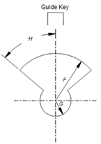
End curve radius: 2.5 mm connectors: SFF connectors: |
PC polishing: 10 – 18 mm APC polishing: 5 – 12 mm PC/APC: 5 – 12 mm |
|
APC angle |
8 ± 0.1° |
|
Features:
|
|
Visual inspection:
|
Allowable Defects and Scratches |
|
|||
|
Zone |
Description |
Diameter |
Defects (diameter) |
Scratches (width) |
|
1a |
Core Zone |
0 to 25 μm |
none |
none |
|
1b |
Cladding Zone |
25 to 120 μm |
any < 2 μm |
none > 3 μm |
|
- |
Adhesive Zone |
120 to 130 μm |
any |
any |
|
2 |
Contact Zone |
130 to 250 μm |
none > 10 μm |
any |
Single mode:
IEC 61300-3-4, Insertion method (C2)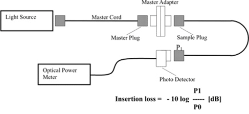 |
Note 5) Eccentricity of core
|
|
|
M |
- |
YYY |
/ |
AAA |
- |
20XXX |
- |
(LLL4) |
/02 |
||||
|
|
|
|
|
|
|
|
|
|
|
|
||||
|
YYY – Master Connector |
|
|
|
20 - cable Ø 2.0 mm |
|
|||||||||
|
AAA3 – Second Connector |
|
|
|
XXX - type of fiber |
|
|||||||||
|
Type |
Description |
|
|
|
S2D |
SM 9/125 µm (G.652D) |
|
|||||||
|
ULC |
LC/UPC |
|
|
|
S7A1 |
SM 9/125 µm (G.657A1) |
|
|||||||
|
NLC |
LC/APC |
|
|
|
|
|
|
|||||||
Note: 1) RL ≥ 58 dB (UPC) and RL ≥ 78 dB (APC) measured with low coherence reflectometry (IEC 61300-3-6 method 3 OLCR)
2) Valid over 1260-1650 nm wavelength range and within operation temperature range -30 to +70°C, tested according to IEC 61300-3-12
3) AAA – second connector types according to relevant datasheets
4) Standard Master patchcord length – 2 m, other on demand
However in case of longer Master patchcord Rayleigh scattering in glass produces small levels of back reflections. Because of backscatter, a link will produce intrinsic reflections which are dependent on the length.
