Master Patchcord
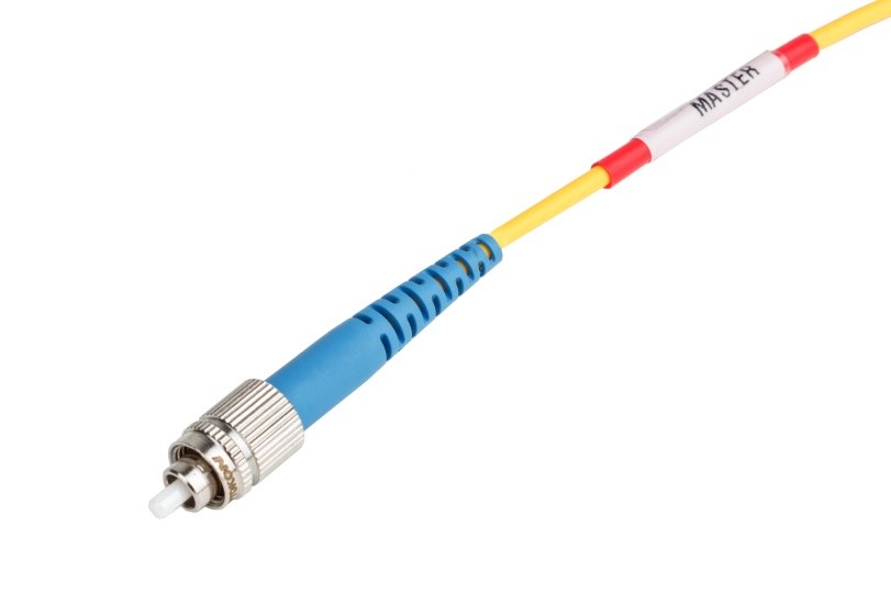
We offer an extensive range of pre-terminated cable assemblies that are 100% tested to ensure conformance with your specifications. These assemblies are used for measuring and manufacturing of fiber optic components and optical network testing. The Master patchcord is equipped with a Master connector according to the specifications below. The master connector is specified with its Serial Number on connector body, which ensures traceability of transmission and geometrical parameters. The second connector is a standard type. For the hybrid patchcord version different types of master and standard connector types are also available.
|
Specifications: |
Single mode |
Multimode |
|
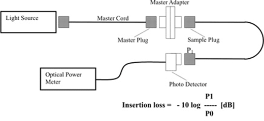
Insertion loss (IL) |
≤ 0.1 dB (λ = 1310, 1550, 1650 nm) |
≤ 0.1 dB (λ = 850, 1300 nm) |
|
Return loss (RL) |
UPC ≥ 55 dB, APC ≥ 65 dB |
PC ≥ 30 dB |
|
Geometrical parameters: |
|
|
|
Eccentricity of core for the center of ferrule |
≤ 0.3 / 0.55 µm |
N/A |
|
Outer diameter of ferrule |
Standard connectors: 2.499 µm |
|
|
|
SFF connectors: 1.249 µm |
|
|
End curve offset |
≤25 µm |
|
|
Fiber height |
-30 to +50 nm |
|
|
End curve radius |
Standard connectors: PC polishing 10 – 18 mm |
|
|
|
APC polishing 5 – 12 mm |
|
|
|
SFF connectors: PC/APC 5 – 12 mm |
|
|
APC angle |
8 ± 0.1° |
N/A |
|
|
|
|
|
Temperature stability (-40°C to +80°C) |
< 0.2 dB |
< 0.2 dB |
|
Mating durability (500 cycles) |
< 0.2 dB |
< 0.2 dB |
|
Cable retention (Ø 2.8 mm) |
100 N |
100 N |
|
|
|
|
|
Material: |
|
|
|
Connector body |
metal, plastic |
metal, plastic |
|
Ferrule material |
full ceramic zirconia |
full ceramic zirconia |
|
Fiber |
9/125 |
50/125; 62.5/125 |
|
Crimp sleeve |
metal |
metal |
|
Boot |
rubber |
rubber |
|
Features:
|
|
|
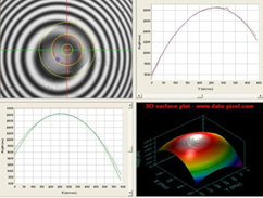
Visual inspection: |
||||
|
Single mode |
||||
|
Allowable Defects and Scratches |
|
|||
|
Zone |
Description |
Diameter |
Defects (diameter) |
Scratches (width) |
|
1a |
Core Zone |
0 to 25 μm |
none |
none |
|
1b |
Cladding Zone |
25 to 120 μm |
any < 2 μm |
none > 3 μm |
|
- |
Adhesive Zone |
120 to 130 μm |
any |
any |
|
2 |
Contact Zone |
130 to 250 μm |
none > 10 μm |
any |
|
Single mode: |
Multimode: |
|
IEC 874-1 4.4.7.4. Method 7 |
IEC 874-1 4.4.7.4. Method 7; |
 |
 |
|
|
|
M |
- |
YYY |
/ |
AAA |
- |
XX XX(S2) – (LL3) |
|||
|
|
|
|
|
|
|
|
|
|
|
||
|
|
connectors |
|
XX – Ø of cable |
XX - type of fiber2 |
|||||||
|
|
YYY – Master connector |
|
20 |
cable Ø 2.0 mm |
OM1 |
MM 62.5/125 µm |
|||||
|
|
AAA1 – standard connector |
|
|
|
OM2-5 |
MM 50/125 µm |
|||||
|
|
code |
type |
|
|
|
S2D |
SM 9/125 µm (G.652D) |
||||
|
LC |
LC |
LC/PC |
|
|
|
S5X4 |
SM 9/125 µm (G.655X) |
||||
|
|
ULC |
LC/UPC |
|
|
|
S7X4 |
SM 9/125 µm (G.657X) |
||||
|
|
NLC |
LC/APC |
|
|
|
|
|||||
|
MU |
MU |
MU/PC |
|
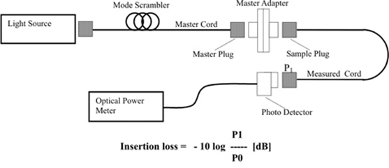
Note: 1) AAA – additional connector types according to CON_13-01_EN - ORD_CODE datasheet2) Mode scrambler shall be used for MM measurement 3) Standard master patchcord length – 2 m or 3 m 4) X – according fiber subtype (e.g. G.657A1)
PC – multimode connectors MASTER ADAPTOR: |
|||||||
|
|
UMU |
MU/UPC |
|
||||||||
|
|
NMU |
MU/APC |
|
||||||||
|
FC |
PC |
FC/PC |
|
||||||||
|
|
UPC |
FC/UPC |
|
||||||||
|
|
NPC |
FC/APC |
|
||||||||
|
SC |
SC |
SC/PC |
|
||||||||
|
|
USC |
SC/UPC |
|
||||||||
|
|
NSC |
SC/APC |
|
||||||||
|
ST |
SL |
ST/PC |
|
||||||||
|
|
USL |
ST/UPC |
|
||||||||
|
LSH |
PE2 |
LSH (E2000)/PC |
|
||||||||
|
|
UE2 |
LSH(E2000)/UPC |
|
||||||||
|
|
NE2 |
LSH(E2000)/APC |
|
||||||||
|
|
|
|
|
|
|
|
|
|
|
|
|
